VIEW POINTS


http://opn.to/a/lJune

An Approach to the Simulation of Wear by Numerical Methods


ABSTRACT

Agricultural machinery has an enemy that threatens its durability and conservation: wear. The wear generates considerable losses of materials, resources and time, with the consequent reduction of the production, leads to the loss of a large quantity of means for its repair, as well as in the elaboration or acquisition of new elements. In this work, an approach towear simulation by numerical methods is made, specifically, the Finite Element Method (FEM) and the Discrete Elements Method (DEM), approaching, in a general way, the benefits of both methods in the analysis of the physical phenomenon, as well as their combination to obtain a closer approximation to the study of contact between bodies.

Keywords: 

ABAQUS; FEM; DEM; wear.


INTRODUCTION

To predict wear and behavior of tools and complex mechanical systems of agricultural machinery, several hundred and thousands of cycles that operate during the process have to be simulated (Hemanth, 2011). However, simulation through computational tools is closely linked to the development of numerical methods and specialized software, which take into account the behavioral equations that govern the process and the main development peculiarities of the phenomenon.

The advances in the development of simulation programs, added to the constant increase of the calculation capacity, have allowed studying the mechanical behavior of the tribological pairs in a more or less simple way, and from these results, to implement the incorporation of models of wear. Thus, in this field, authors such as Xie et al.(2005), Hernández et al. (2007),Negrín et al. (2008), Hemanth(2011),Pérez et al.(2014), Saucedo (2014), Zuo et al.(2014), Da Silva (2016), Attanasio et al.(2017) and Ramadhani (2018), have executed important works of wear simulation using the Finite Element Method. At the same time, other authors, including Hernández et al.(2005), Kanavalli (2006),Ding et al. (2008), Cruzado et al.(2010, 2013), Hernández and Riera (2014), Zegatti (2016) and Goreham and Brown (2017), have made significant contributions to the wear simulation in FEM using the ABAQUS computer program, through the implementation of the UMESHMOTION subroutine.They have used the tool calledLangrangeana-Euleriana Arbitrary Adaptive Mesh ("ALE MallaAdaptativa") that allows implementing the Archard wear model and the Dissipated Energy model, which currently have a great acceptance in the analysis of this phenomenon.

On the other hand, Recarey et al.(2001), Burrel(2003),Gutiérrez and Fuentes (2007),Sánchez et al.(2009, 2014), Champagne et al.(2014) and Perazzo et al. (2016), have carried out important wear studies using the Discrete Element Method, which is a numerical method capable of specifying the behavior of geometrically defined media by particles.

Similarly, Oñate et al. (2005), Ramalho (2008), Nitka et al.(2011), Stransk and Jirasék (2012),Morales (2013), Taforel et al.(2015) and Sun et al. (2016), have obtained results that show that the combined FEM-DEM methodology is an efficient tool to analyze the wear behavior due to fracture. That is because, in most of these problems, the phenomenon appears only in certain parts of the domain (contact zone) and the rest has a behavior that can be represented as continuous. Hence, the interest to model this type of problems with the method of discrete elements (DEM) for the area of wear and FEM for the rest of the domain, taking advantage of the benefits both methods offer.

METHODS

Wear patterns. The model of Archard is the best-known and used wear model in academic and engineering environments to estimate wear on surfaces and parts. According to Zegatti (2016), this model considers that the volume of material removed (V), obtained from the interaction of two bodies, is directly proportional to the normal load applied to the body (P) and to the sliding distance (s), and inversely proportional to the hardness of the material (H). A dimensionless coefficient (K), called the wear coefficient, is introduced to take into account different materials, geometries and applied loads. The ratio between this coefficient and the hardness is replaced by a specific wear coefficient (k), this being the only property of the material present in the Archard wear law represented in Equation (1).

This equation allows calculating the global wear volume, however, to use the analysis programs by finite elements and discrete elements it is necessary to estimate the wear locally. In this sense, McColl et al. (2004) cited by Zegatti (2016), developed a modified version by applying Equation (1) locally to an area dA and for an increase in sliding distance ds. Then, bydividing both sides of the equation by dA, Equation (2) is achieved, obtaining the infinitesimal wear height (dh), and the normal contact pressure observed on the contact surfaces p(x).

When this equation is applied in the FEM, the infinitesimal height (dh) represents the nodal depth of the material that will be removed (Δh), after traveling a relative sliding distance (Δs). In the absence of a method to calculate the wear coefficient locally, this author considers that the local wear coefficient is the same used in the determination of the global wear volume, there being no great implications in the results on account of this consideration, so therefore, the formulation adopted for use in the FEM analysis is presented below.

Finally, Equation (4) is the formulation currently used to compute the nodal depth of wear at each increment, affected by the wear accelerator (ΔN), which uses the results generated in a cycle to estimate the wear for a greater number of cycles, reducing the computation time and not generating instabilities or great divergences in the results.

The Dissipated Energy model takes into account the energy consumed in the wear process, since a specific amount of energy is necessary to remove a certain volume of material. Here it is considered that the volume of wear (V) is obtained by multiplying the dissipated energy by the accumulated friction in the interface (ΣEd), by a wear coefficient of the accumulated energy (α) as shown in Equation (5). This energy is obtained by calculating the generated work by the tangential force (Q) along the traveled distance as seen in the Equation (6).

As in the Archard model, the dissipated energy can be analyzed locally to obtain the nodal depth of the material that will be removed, leaving the necessary formulation expressed in Equation (7), where the only difference observed between the two models is in the inclusion of the friction coefficient, whenever q(x)=μ.p(x) .

RESULTS AND DISCUSSION

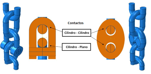
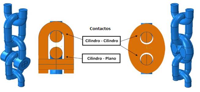
Modeling in FEM. To simulate the process, it is necessary to verify the correct positioning of the bodies in contact, to guarantee that the initial interaction between them is carried out successfully. Besides,it is necessary to define the properties of the material and the contact properties, where the slave and master surfaces area detailed, just in the region where the contact willoccurin fact, so that unnecessary computational time is not required. In the contact zones (Figure 1), where the most critical values of the tension, deformation and pressure distribution fields are verified, a more detailed refinement of the mesh is performed.
2071-0054-rcta-28-04-e10-gf1.png

FIGURE 1. 

Contact configurations observed between connectors and anchor line links Zegatti (2016).

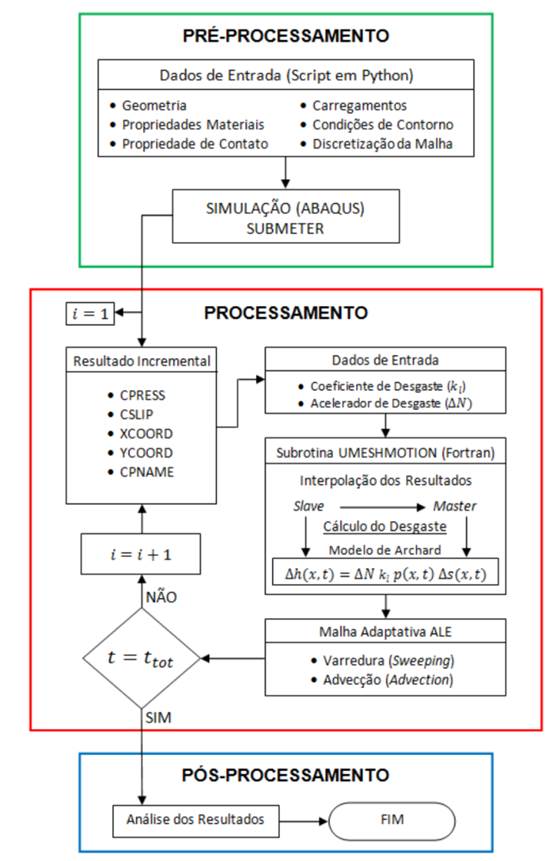
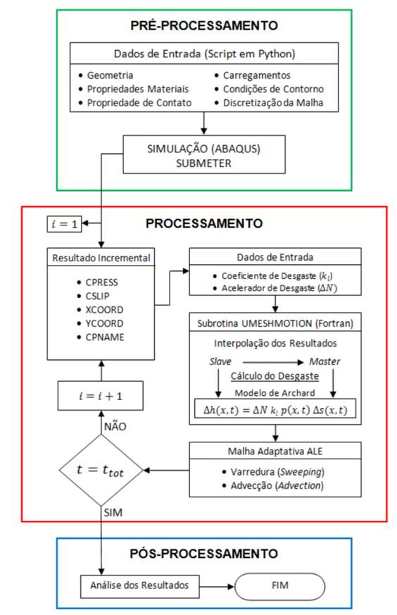
In ABAQUS program, the implementation of the wear model is carried out through the UMESHMOTION subroutine (Figure 2) by means of the ALE adaptive mesh, which is used to improve the convergence of the mesh in simulations where large distortions in finite elements are observed. By means of a mesh remapping, the adaptive mesh repositions the nodes for a more appropriate position, improving the convergence and combining the characteristics of a purely Lagrangean analysis and a purely Eulerian one, which allows a high quality mesh to be obtained during all the simulation, the same when large deformations or material losses occur.
2071-0054-rcta-28-04-e10-gf2.jpg

FIGURE 2. 

Implementation flow chart of thelocal wear Zegatti (2016).

The process of implementation of the local wear begins in the pre-processing, where the modeling of the problem is carried out. In this stage, the geometry, the properties of the material, the properties of the contact, the loads, the conditions of contour and the discretization of the mesh are input data for the creation of a script in the Python language and, by means of this code, the simulationstarts. Then,it is expected that it reaches the step where the application of the displacement cycles begins. Immediately after the first increment converges, the results obtained in each node are used to serve as data input to the subroutine. Together with these results, the local wear coefficient (kl) and the wear accelerator (ΔN) are also used as input data for the subroutine, written in FORTRAN programming.

The nodal displacement referring to wear is applied in the normal direction to the surface on which the node is located. To calculate that depth of wear, the modified Archard method presented by McColl et al. (2004), is used. With all these computed values, the adaptive mesh ALE performs the processes of sweeping and advection to make effective the remappingof the mesh. After this stage, new values of the field of distribution of stresses and distribution of contact pressures are recalculated according to the configurationused. Finally, in case that the simulation time is less than the total expected time, the next time increment is performedand, if not, the simulation is finished and the data are available for the analysis of the results Zegatti (2016).

Modeling in DEM. To implement the wear model in a DEM code and to model the loss of material of the piece from the information of the Archard model, it is necessary to specify the information of the wear patternto be visualized. Because of that, it is necessary to develop an own DEM code that grants the required flexibility for this type of specific application (Perazzo et al., 2016).

The discrete element method is implemented as a cyclical algorithm, where the laws of motion of each particle, a law of force-displacement in each contact and a constant updating of positions are applied. From the knowledge of the position and velocity of the particles, the contacts of different particles are updated and the modified Hertz contact model is applied to determine the reaction forces (Hu et al., 2010). The Archard wear model takes information on the speeds and forces to predict the volume loss associated with abrasive wear on the machine element. With the information of the forces and torques, the new speeds and positions are calculated using a direct method of temporary integration.

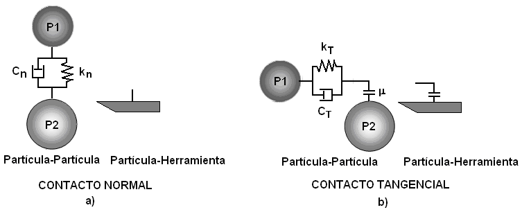
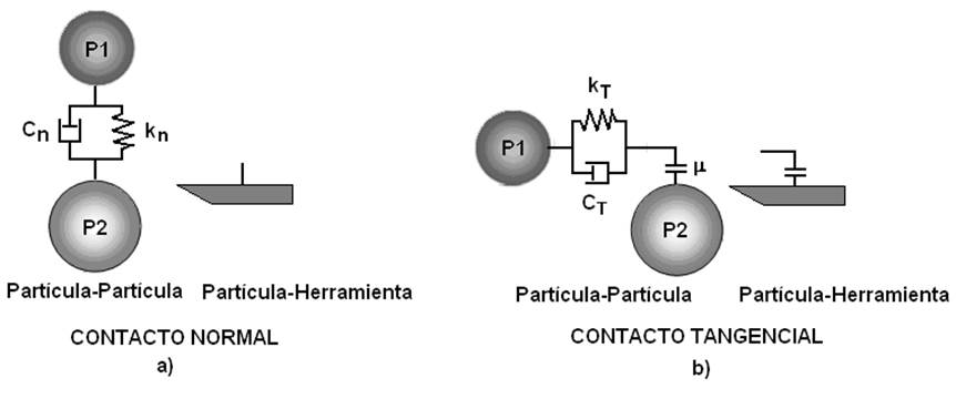
The constitutive model of contact between the particles of the medium is formulated taking into account that in the normal direction of contact, they will have a viscoelastic reaction that is given by the inclusion of the normal stiffness (kn) and the viscous constant in the normal direction (Cn). In the tangential sense of the contact, the constitutive model comprises an elastic reaction of the medium represented by the tangential stiffness (k T ), the viscous constant in the tangential direction, in addition to the action of the interparticle friction given by the Coulomb coefficient (μ)that, the internal friction of the medium,will be taken as data. In the case of the constitutive model of contact between the particles of the medium and the tool (Figure 3), it is formulated in a similar way, with the difference that the friction coefficient to be taken as data corresponds to the external friction related to the average friction -tool.
2071-0054-rcta-28-04-e10-gf3.jpg

FIGURE 3. 

Constitutive models of contact, a) Among the particles of the medium, b) between the medium particles and the tool (Sánchez et al., 2014).

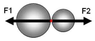
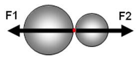
The action-reaction forces that act among the particles of the medium during the interaction or between the particles of the medium and the tool (Figure 4) will be determined from Newton's third law. The determination of the contact forces (Fn) and (F T ) depend on the equilibrium equations, either between the particles of the medium, or between the particles of the medium and the tool.
2071-0054-rcta-28-04-e10-gf4.jpg

FIGURE 4. 

Representation of theaction-reaction forces that act among the particles of the medium during the interaction or between the particles of the medium and the tool(Sánchez et al., 2014).

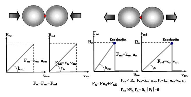
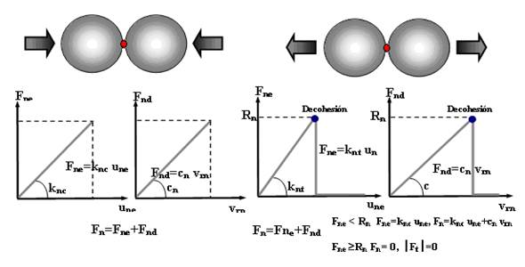
The constitutive models of contacts presuppose the existence of both elastic and viscous damping. Therefore, the normal force (Fn) will be composed of a normal elastic force (Fne) and a normal damped force (Fnd).

The breaking of the contacts between particles is mainly due to the application of external loads to the system, the action of the volumetric forces and the reaction forces that generate the collisions between particles. This rupture occurs once the magnitude of the maximum cohesive force of the contact in the tangential or normal direction is exceeded ( Fn>RnorFT>RT ). It will be fulfilled as a condition that the contacts cannot be restored after breaking (Figure 5).
2071-0054-rcta-28-04-e10-gf5.jpg

FIGURE 5. 

Normal contact forces versus relative displacement in the normal direction and normal damping force versus relative velocity in the normal direction (compression or traction) (Recarey et al., 2001).

Combination FEM - DEM. Coupling the FEM and the DEM is a possibility to take advantage of the benefits presented by both methods,considering the problems that cannot be approached by only one of them. The idea is to model part of the domain with DEM, for example, where a granular medium is present, and the other partwith FEM, where the use of simple triangular or tetrahedral elements to model the continuous domain is very useful from the point of view of simplicity of geometry. Examples of this are the problems in which there is interaction of solids and structures with granular media (Oñate et al., 2005).

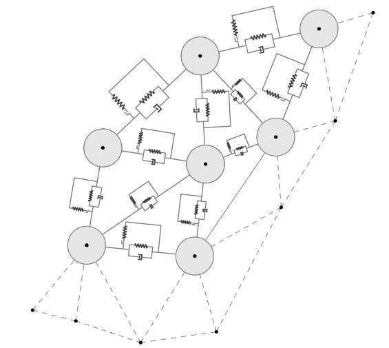
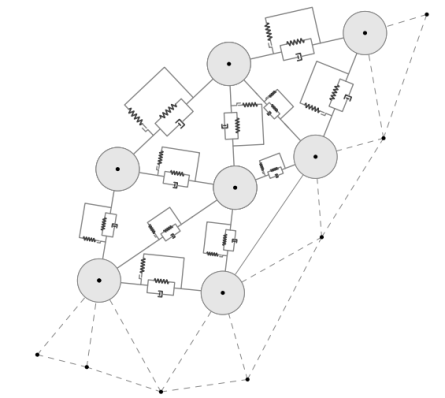
According to Morales (2013), a discretized continuous medium with FEM can be seen as a discretization with DEM with virtual elements of FEM as shown in Figure 6.
2071-0054-rcta-28-04-e10-gf6.png

FIGURE 6. 

DEM virtual elements in FEM discretization (Morales, 2013).

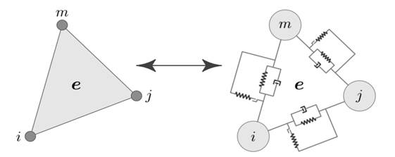
Given the main characteristics of both methodologies, it is convenient to start with the formulation of FEM finding displacements, tensions, deformations and all those variables of interest. Then particles with center in the nodes i,j,m and their respective radios,ri, rj,rm, are assigned to relate the contact force between each pair of particles; that is, the contact force of DEM is modeled at each edge of the triangular element of FEM (Figure 7).
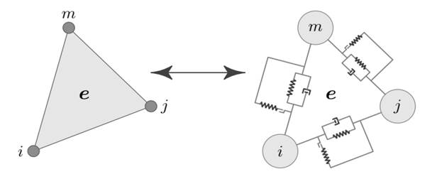
2071-0054-rcta-28-04-e10-gf7.jpg

FIGURE 7. 

Relationship between the FEM and DEM models (Morales, 2013).

To model this contact force from the properties of FEM, each element of the FEM discretization has an associated elementary stiffness matrix. Then, known the rigidity that each edge provides to the FEM formulation, it is possible to model the force of contact in these. To determine which edges will suffer some damage, a breaking criterion is adopted based on the evaluated stresses and deformations in all edges of the discretization. When the breaking criterion is reached, particles are created in their nodes and their corresponding radii are assigned; then, it is necessary to eliminate the contribution that this edge contributes to the rigidity matrices of those elements that share it or of that element that contains it when this edge is at the frontier of the study domain (Morales, 2013).

Finally, the elementary matrices whose edges have suffered some damage in the global stiffness matrix are assembled, passing the damage that each edge undergoes to the global system, in such a way that in the next iteration of the simulation process, a domain with a located damage is considered. In the case that dl = 1, the domain suffers a fracture, also localized.

CONCLUSIONS

The use of UMESHMOTION subroutine in FEM programs allows local wear to be computed after each increment of time and not after an entire displacement cycle and to perform the meshing update, it is not necessary to stop the simulation and restart it again.

One of the main points to be addressed in the numerical simulations carried out by means of the discrete element method is that it allows the material to be brought to a breaking stress, and thus be able to simulate this breakage and wear.

The combination of finite elements and discrete elements defines a powerful tool that is presented as an idealization that takes the strengths of each method and groups them into one, where the discretization of the particles is done using the finite element technique, while the modeling of the contacts between each particle is done using the discrete element technique.

 

REFERENCES

ATTANASIO, A.; FAINI, F.; OUTEIRO, J.C.: “FEM simulation of tool wear in drilling”, Procedia CIRP, 58: 440-444, 2017, ISSN: 2212-8271, DOI: 10.1016/j.procir.2017.03.249.

BURREL, S.: Estudio del problema de desgaste empleando el método de las partículas, Universidad Politécnica de Cataluña, Barcelona, Escuela Técnica Superior de caminos, canales y puertos de Barcelona., Master Science Thesis, Barcelona, España, 27-44 p., 2003.

CHAMPAGNE, M.; ACUTIS, M.; BERTHIER, Y.: “Modeling wear for heterogeneous bi-phasic materials using discrete elements approach”, Journal of Tribology, 136(2): 021603, 2014, ISSN: 0742-4787.

CRUZADO, A.; LEEN, S.; URCHEGUI, M.; GÓMEZ, X.: “Finite element simulation of fretting wear and fatigue in thin steel wires”, International Journal of Fatigue, 55: 7-21, 2013, DOI: http://dx.doi.org/10.1016/j.ijfatigue.2013.04.025.

CRUZADO, A.; ZABALA, A.; URCHEGUI, M.; GÓMEZ, X.: “Definición de una metodología optimizada para la simulación del desgaste en materiales metálicos”, Revista de Metalurgia, 46(Extra): 106-114, 2010, ISSN: 0034-8570, E-ISSN: 1988-4222, DOI: 10.3989/revmetalmadrid.11XIIPMS.

DA SILVA, M.N.L.: Estudo do desgaste de componentes de sistemas de amarração de plataformas offshore, Universidade de Brasília, Eng. Thesis, Engenheiro Mecânico, Brasília, Brasil, 75 p., 2016.

DING, J.; LEEN, S.; WILLIAMS, E.; SHIPWAY, P.: “Finite element simulation of fretting wear-fatigue interaction in spline couplings”, Tribology-Materials, Surfaces & Interfaces, 2(1): 10-24, 2008, ISSN: 1751-5831, DOI: 10.1179/175158308x320791.

GOREHAM, V.C.M.; BROWN, T.D.: “Finite Element Wear Simulation of the Charite Total Disc Replacement, Including Cross-Shear,”, [en línea], En: Poster No. 2417, 55th Annual Meeting of the Orthopaedic Research Society, Ed. University of Lowa, Lowa City, LA, USA, p. 1, 2017, Disponible en:Disponible en:https://www.ors.org/Transactions/55/2417.pdf ,[Consulta: 5 de marzo de 2018].

GUTIÉRREZ, S.A.; FUENTES, B.D.: “Estudio del desgaste en materiales mediante el Metodo de Elementos Discretos”, [en línea], En: 8o Congreso Iberoamericano de Ingeniería Mecánica, Cusco , (23 al 25 de Octubre), vol. 23, Cusco, pp. 1-12, 2007, Disponible en:Disponible en:https://upcommons.upc.edu/.../CIBIM8 ,[Consulta: 21 de enero de 2018].

HEMANTH, J.: “Finite element wear behavior modeling of al/al2sio5/c chilled hybrid metal matrix composites (CHMMCS)”, Materials Sciences and Applications, 2(07): 878-890, 2011, DOI: 10.4236/msa.2011.27118.

HERNÁNDEZ, R.; RIERA, C.M.D.: “Simulación de fenómenos de desgaste mediante el uso de ABAQUS/SCRIPTING”, [en línea], En: XII Reunión de Usuarios de Abaqus, CTM-Centre Tecnològic, Barcelona, España, p. 8, 2014, Disponible en:Disponible en:https://www.researchgate.net/publication/267705327.pdf ,[Consulta: 16 de febrero de 2018].

HERNÁNDEZ, R.; RIERA, C.M.D.; PRADO, J.M.: “Modelización y simulación del desgaste en aceros de herramientas”, [en línea], En: X Reunión de Usuarios de ABAQUS, CTM-Centre Tecnològic, Barcelona, España, p. 7, 2005, Disponible en:Disponible en:https://upcommons.upc.edu/bitstream/handle/2117/14533/2005-ABAQUS-DESGASTE%20HERRAMIENTAS.pdf , [Consulta: 16 de febrero de 2018].

HERNÁNDEZ, R.R.; CRUZ, M.; CASELLAS, P.D.; RIERA, C.M.D.; PRADO, P.J.M.: “Evaluación del comportamiento a desgaste en aceros de herramienta: simulación por ordenador y verificación experimental”, En: Anales de mecánica de la fractura, vol. 2, pp. 619-623, 2007, ISBN: 0213-3725.

HU, G.; HU, Z.; JIAN, B.; LIU, L.; WAN, H.: “On the determination of the damping coefficient of non-linear spring-dashpot system to model Hertz contact for simulation by discrete element method”, En: 2010 WASE International Conference on Information Engineering, Ed. IEEE, vol. 3, pp. 295-298, 2010, ISBN: 1-4244-7507-4.

KANAVALLI, B.: Application of user defined subroutine UMESHMOTION in ABAQUS for simulating dry rolling/sliding wear, Royal Institute of Technology (KTH), Master of Science (Scientific Computing), Stockholm, Sweden, 2006.

MCCOLL, I.; DING, J.; LEEN, S.: “Finite element simulation and experimental validation of fretting wear”, Wear, 256(11-12): 1114-1127, 2004, ISSN: 0043-1648.

MORALES, Q.M.: Formulación de elementos finitos y elementos discretos, [en línea], Centro de Investigación en Matemáticas. Centro Internacional de Métodos Numéricos en Ingeniería, MSc. Thesis, Barcelona, España, 91 p., 2013, Disponible en:Disponible en:https://www.cimat.mx/sites/default/files/PDFs/A_CIMNE_CIMAT/DEM.pdf ,[Consulta: 14 de marzo de 2018].

NEGRÍN, I.L.; SOUZA, M.R.; PÉREZ, A.E.: “Estudio del contacto entre un pentrador rígido y una probeta de aluminio considerando carga normal y desplazamiento tangencial usando el metodo de los elementos finitos”, Revista Iberoamericana de Ingeniería Mecánica, 12(1): 15-23, 2008.

NITKA, M.; COMBE, G.; DASCALU, C.; DESRUES, J.: “Two-scale modeling of granular materials: a DEM-FEM approach”, Granular Matter, 13(3): 277-281, 2011, ISSN: 1434-5021, DOI: 10.1007/s10035-011-0255-6.

OÑATE, E.; LABRA, C.; ZÁRATE, F.; ROJEK, J.; MIQUEL, J.: “Avances en el desarrollo de los Métodos de Elementos Discretos y de Elementos Finitos para el análisis de problemas de fractura”, En: Anales de mecánica de la fractura , vol. 22, pp. 27-34, 2005.

PERAZZO, F.; KNOP, F.; MASCARÓ, P.; PLACENCIA, G.: “Modelación numérica de la tasa y el patrón de desgaste abrasivo mediante el método de elementos discretos”, Mecánica Computacional, 34: 1013-1026, 2016.

PÉREZ, R.E.A.; MUÑOZ, T.G.E.; SOUZA, M.R.; NEGRÍN, H.L.I.: “Simulación de un sistema tribológico formado por sustrato recubrimiento rugoso usando métodos numéricos”, Ingeniería Mecánica, 17(1): 48-56, 2014, ISSN: 1815-5944.

RAMADHANI, B.W.: FEM Modelling and Simulation of Production Casing with Local Wear Damage, [en línea], Stavanger University, Master’s thesis, Norway, 2018, Disponible en:Disponible en:https://brage.bibsys.no/xmlui/handle/11250/2570231 , [Consulta: 5 de enero de 2019].

RAMALHO, A.: “A geometrical model to predict the wear evolution of coated surfaces”, Wear, 264(9-10): 775-780, 2008, ISSN: 0043-1648.

RECAREY, M.C.A.; OÑATE, E.; MIGUEL, J.; ROJEK, J.; ZARATE, F.; (primero): Simulación de problemas de desgaste en la interacción herramienta de corte terreno empleando el Método de los Elementos Discretos, Inst. Universidad Central de las Villas, Santa Clara, Villa Clara, Cuba, 25 p., 2001.

SÁNCHEZ, I.A.L.; HERRERA, S.M.; RECAREY, M.C.A.; IGLESIAS, C.C.: “Bases teóricas para la simulación del desgaste de los órganos de trabajo de los aperos de labranza mediante el Método de los Elementos Distintos (MED)”, Revista Ciencias Técnicas Agropecuarias, 23(2): 81-88, 2014, ISSN: 1010-2760, e-ISSN: 2071-0054.

SÁNCHEZ, I.A.L.; RECAREY, M.C.A.; HERRERA, S.M.: “Simulación del desgaste en 3D durante la interacción herramienta de corte-terreno mediante el Método de los Elementos Discretos (MED)”, Revista Ciencias Técnicas Agropecuarias, 18(1): 27-31, 2009, ISSN: 1010-2760, e-ISSN: 2071-0054.

SAUCEDO, D.J.J.: Análisis del desgaste en engranes aplicando el Método de Elementos Finitos, Universidad Autónoma de Querétaro, MSc. Thesis (Mecatrónica), Querétaro, México, 2014.

STRANSK, J.; JIRASÉK, M.: “Open source FEM-DEM coupling”, En: 18th International Conference Engineering Mechanics, Svratka, Czech Republic, May 14 - 17, vol. Paper # 12012, Svratka, Czech Republic, pp. 1237-1251, 2012.

SUN, G.; SUI, T.; KORSUNSKY, A.M.: “Review of the hybrid finite-discrete element method (FDEM)”, En: The World Congress on Engineering , June 29 - July 12, vol. 2, London, U. K, 2016.

TAFOREL, P.; RENOUF, M.; DUBOIS, F.; VOIVRET, J.C.: “Finite element-discrete element coupling strategies for the modelling of ballast-soil interaction”, International Journal of Railway Technology, ser. hal-01279251, 4(2): 73-95, 2015, DOI: 10.4203/ijrt.4.2.4.

XIE, L.-J.; SCHMIDT, J.; SCHMIDT, C.; BIESINGER, F.: “2D FEM estimate of tool wear in turning operation”, Wear, 258(10): 1479-1490, 2005, ISSN: 0043-1648, DOI: 10.1016/j.wear.2004.11.004.

ZEGATTI, M.: Estudo da Influência do Desgaste na Falha Prematura de Componentes de Linhas de Ancoragem, Universidade de Brasília, Departamento de Engenharia Mecânica, Mestrado em Ciências Mecânicas, Brasília, DF, Brasil, 128 p., 2016.

ZUO, S.; NI, T.; WU, X.; WU, K.; YANG, X.: “Prediction procedure for wear distribution of transient rolling tire”, International Journal of Automotive Technology, 15(3): 505-515, 2014, ISSN: 1229-9138, DOI: 10.1007/s12239-014-0053-3.


Rigoberto Antonio Pérez Reyes, Profesor Auxiliar, Applicanttodoctorate,Universidad de Ciego de Ávila Máximo Gómez Báez, Facultad de Ciencias Técnicas, Ciego de Ávila, Cuba. Carretera a Morón Km 9½, CP: 65300, Teléfono (33) 217009, Fax 5333 225768, e-mail: rigoberto@unica.cu

Jorge Douglas Bonilla Rocha,e-mail: jorgedbr@unica.cu

Lázaro Antonio Daquinta Gradaille, e-mail: adaquinta@unica.cu

Carlos Alexander Recarey Morfa,e-mail: recarey@uclv.edu.cu

Anibal Sánchez Numa,e-mail: anibal@unica.cu

The authors of this work declare no conflict of interest.

This article is under license Creative Commons Attribution-NonCommercial 4.0 International (CC BY-NC 4.0)

The mention of commercial equipment marks, instruments or specific materials obeys identification purposes, there is not any promotional commitment related to them, neither for the authors nor for the editor.


PUNTOS DE VISTA


Un acercamiento a la simulación del desgaste por métodos numéricos


RESUMEN

La maquinaria agrícola tiene un enemigo que atenta contra su durabilidad y conservación: el desgaste.El desgaste genera considerables pérdidas de materiales, recursos y tiempo, con la consiguiente disminución de la producción, conlleva a la pérdida de gran cantidad de medios para su reparación, así como en la elaboración o adquisición de nuevos elementos.En este trabajo se realiza un acercamiento a la simulación del desgaste por métodos numéricos, específicamente el Método de los Elementos Finitos (MEF) y el Método de los Elementos Discretos (MED), abordando de manera general las bondades de ambos métodos en el análisis del fenómeno físico, así como su combinación para obtener una mayor aproximación al estudio del contacto entre los cuerpos.

Palabras clave: 

ABAQUS; MEF; MED; desgaste.


INTRODUCCIÓN

Para predecir el desgaste y el comportamiento de herramientas y sistemas mecánicos complejos de la maquinaria agrícola, varioscientos y miles de ciclos que operandurante el proceso tienen que ser simulados.(Hemanth, 2011).Sin embargo, la simulación a través de herramientas computacionales, está muy ligada al desarrollo de los métodos numéricos y los software especializados,que toman en cuenta las ecuaciones de comportamiento que gobiernan el proceso y las principales particularidades deldesarrollo del fenómeno.

Los avances en el desarrollo de programas de simulación, sumado al constante aumento de la capacidad de cálculo, han permitido estudiar el comportamiento mecánico de los pares tribológicos de una manera más o menos simple, y a partir de estos resultados, implementar la incorporación de modelos de desgaste. Así, en este campo, autores como Xie et al.(2005); Hernández et al.(2007); Negrín et al.(2008); Hemanth(2011); Pérez et al.(2014); Saucedo(2014); Zuo et al.(2014); Da Silva (2016); Attanasio et al.(2017); Ramadhani(2018), han ejecutado importantes trabajos de simulación del desgaste utilizando el Método de los Elementos Finitos.Al mismo tiempo, otros autores, entre los que se encuentran Hernández et al.(2005); Kanavalli(2006); Ding et al.(2008); Cruzado et al.(2010, 2013); Hernández y Riera(2014); Zegatti(2016); Goreham y Brown(2017),han realizado significativas contribuciones a la simulación del desgaste en MEF utilizando el programa computacional ABAQUS, mediante la implementación de la subrutina UMESHMOTION, por medio de la herramienta denominada Malla Adaptativa Arbitraria Langrangeana-Euleriana(“ALEAdaptiveMesh”) que permite implementar el modelo de desgaste de Archard y el de la Energía Disipada, los cuales cuentan,en la actualidad, con gran aceptación en el análisis de este fenómeno.

Por otra parte, Recarey et al.(2001); Burrel(2003); Gutiérrez y Fuentes (2007); Sánchez et al.(2009, 2014); Champagne et al.(2014); Perazzo et al.(2016), han realizado importantes estudios del desgaste mediante el Método de los Elementos Discretos, el cual es un método numérico capaz deprecisar el comportamiento de medios definidos geométricamente por partículas.

De igual modo, Oñate et al.(2005); Ramalho (2008); Nitka et al.(2011); Stransk y Jirasék(2012); Morales (2013); Taforel et al.(2015); Sun et al.(2016), han obtenido resultados que muestran que la metodología MEF-MED combinada es una herramienta eficiente para analizar el comportamiento del desgaste por fractura, pues en la mayoría de estos problemas el fenómeno aparece sólo en ciertas partes del dominio (zona de contacto) y el resto tiene un comportamiento que puede ser representado como continuo, de ahí el interés de modelar este tipo de problemas con el método de elementos discretos (MED) para la zona del desgaste y la fractura y MEF para el resto del dominio, aprovechando de esta forma las bondades que ofrecen ambos métodos.

DESARROLLO DEL TEMA

Modelos de desgaste. El modelo de Archard es el modelo de desgaste más conocido y utilizado en los medios académicos e ingenieriles para estimar el desgaste en superficies y piezas. Según Zegatti(2016), este modelo considera que el volumen de material removido (V), obtenido de la interacción de dos cuerpos, es directamente proporcional a la carga normal aplicada al cuerpo (P) y a la distancia de deslizamiento (s), e inversamente proporcional a la dureza del material (H). Un coeficiente adimensional (K), denominado coeficiente de desgaste, es introducido para tener en cuenta los diferentes materiales, geometrías y cargas aplicadas. La razón entre este coeficiente y la dureza es sustituida por un coeficiente de desgaste específico (k), siendo esta la única propiedad del material presente en la ley de desgaste de Archard representada en la ecuación (1)

Esta ecuación permite calcular el volumen de desgaste global, sin embargo, para utilizar los programas de análisis por elemento finito y elemento discretose hace necesario estimar el desgaste localmente. En este sentido, McColl et al.(2004) citado por Zegatti(2016), desarrolló una versión modificada aplicando la ecuación (1) localmente a un área dA y para un incremento de distancia de deslizamiento ds, luego, dividiendo ambos lados de la ecuación por dA, logra la ecuación (2), obteniendo la altura de desgaste infinitesimal (dh), y la presión de contacto normal observada en la superficies de contacto p(x).

Cuando se aplica esta ecuación en el MEF, se tiene que la altura infinitesimal (dh) representa la profundidad nodal del material que será removido (Δh), después de recorrida una distancia de deslizamiento relativa (Δs). Por no existir ningún método que calcule el coeficiente de desgaste localmente, este autor considera que el coeficiente de desgaste local es el mismo utilizado en la determinación del volumen de desgaste global, no existiendo grandes implicaciones en los resultados por cuenta de esta consideración, por lo tanto, la formulación adoptada para la utilización en análisis MEF se presenta a continuación.

Finalmente, la ecuación (4) es la formulación utilizada actualmente para computar la profundidad nodal de desgaste a cada incremento, afectada por el acelerador de desgaste (ΔN), el cual utiliza los resultados generados en un ciclo para estimar el desgaste para un número mayor de ciclos, reduciendo el tiempo de cómputo y no generando inestabilidades ni grandes divergencias en los resultados.

El modelo de la Energía Disipada tiene en cuenta la energía consumida en el proceso de desgaste, toda vez que para remover cierto volumen de material es necesario una cantidad de energía específica. Aquí se considera que el volumen de desgaste (V) es obtenido multiplicando la energía disipada por el rozamiento acumulada en la interface (∑E d ), por un coeficiente de desgaste de la energía acumulada (α) como se muestra en la ecuación (5). Esta energía es obtenida calculando el trabajo generado por la fuerza tangencial(Q)a lo largo de la distancia de deslizamiento recorrida como se aprecia en la ecuación (6).

Al igual que en el modelo de Archard, la energía disipada puede ser analizada localmente para obtener la profundidad nodal del material que será removido, quedando la formulación necesaria expresada en la ecuación (7), donde la única diferencia observada entre los dos modelos está en la inclusión del coeficiente de fricción, toda vez que q(x)=μ.p(x) .

RESULTADOS Y DISCUSIÓN

La modelación en MEF. Para simular el proceso, hay que verificar el correcto posicionamiento de los cuerpos en contacto, para garantizar que la interacción inicial entre ellos sea efectuada con éxito, además de definir las propiedades del material y las propiedades de contacto, donde se precisan las superficies slave y master apenas en la región donde el contacto irá de hecho a ocurrir, para que no sea exigido tiempo computacional innecesario. En las zonas de contacto (Figura 1), donde se verifican los valores más críticos de los campos de tensión, deformación y distribución de presión, se realiza un refinamiento más detallado de la malla.

2071-0054-rcta-28-04-e10-gf11.jpg

FIGURA 1. 

Configuraciones de contacto observadas entre conectores y eslabones de líneas de anclaje Zegatti(2016).

En el programa ABAQUS, la implementación del modelo de desgaste se realiza a través de la subrutina UMESHMOTION (Figura 2) por medio del mallado adaptativo ALE, el cual se utiliza con el objetivo de mejorar la convergencia de la malla en simulaciones donde se observan grandes distorsiones en los elementos finitos. Por medio de un remapamiento de la malla, la malla adaptativa recoloca los nodos para una posición más apropiada, mejorando la convergencia y combinando las características de un análisis puramente Lagrangeanao y uno puramente Euleriano, lo que permite que se tenga una malla de alta calidad durante toda la simulación, lo mismo cuando ocurren grandes deformaciones o pérdidas de material.

2071-0054-rcta-28-04-e10-gf12.jpg

FIGURA 2. 

Flujograma de implementación del desgaste local Zegatti(2016).

El proceso de implementación del desgaste local se inicia en el pre-procesamiento donde se realiza la modelación del problema. En esta etapa, la geometría, las propiedades del material, las propiedades del contacto, las cargas, las condiciones de contorno y la discretización de la malla son datos de entrada para la creación de un guión(Script) en el lenguaje Python y por medio de este código se inicia la simulación. Luego, se espera a que el mismo alcance el paso donde se inicia la aplicación de los ciclos de desplazamientos. Inmediatamente que el primer incremento converge, se utilizan los resultados obtenidos en cada nodo para servir de entrada de datos a la subrutina.Conjuntamente con estos resultados, el coeficiente de desgaste local (k l ) y el acelerador de desgaste (ΔN), también son utilizados como datos de entrada para la subrutina, escrita en programación FORTRAN.

El desplazamiento nodal, referente al desgaste es aplicado en la dirección normal a la superficie en la que se encuentra el nodo. Para calcular esa profundidad de desgaste se utiliza el método modificado de Archard presentado por McColl et al. (2004). Con todos esos valores computados, la malla adaptativa ALE realiza los procesos de barredura (Sweeping) y advesión (Advection) para hacer efectivo el remapamiento de la malla. Concluida esta etapa, nuevos valores del campo de distribución de tensiones y distribución de presiones de contacto son recalculados de acuerdo con la configuración desgastada. Finalmente, en caso de que el tiempo de simulación sea menor que el tiempo total esperado, se parte para el próximo incremento de tiempo y, en caso contrario, la simulación es finalizada y se disponen los datos para el análisis de los resultados Zegatti(2016).

La modelación en MED.Para implementar el modelo de desgaste en un código MED y modelar la pérdida de materialde la pieza a partir de la información del modelo de Archard, hay que especificar lainformación que se desea visualizar del patrón de desgaste, por lo que es necesario desarrollar uncódigo MED propio que otorga la flexibilidad necesaria para este tipo de aplicación enespecífico (Perazzo et al., 2016).

El método de elemento discreto se implementa como un algoritmo cíclico, donde seaplican las leyes de movimiento de cada partícula, una ley de fuerza-desplazamiento en cadacontacto y una actualización constante de posiciones. A partir del conocimiento de la posición y velocidad de las partículas, se actualizan loscontactos de diferentes partículas y se aplica el modelo de contacto de Hertz modificado para determinar las fuerzas de reacción (Hu et al., 2010). El modelo de desgaste de Archardtoma información de las velocidades y fuerzas para predecir la pérdida devolumen asociado al desgaste abrasivo sobre el elemento de máquina. Con la información delas fuerzas y torques, se calculan las nuevas velocidades y posiciones usando un método directode integración temporal.

El modelo constitutivo de contacto entre las partículas del medio se formula tomando en cuenta que en la dirección normal del contacto las mismas tendrán una reacción viscoelástica que está dada por la inclusión de la rigidez normal (k n ) y la constante viscosa en la dirección normal (C n ). En el sentido tangencial del contacto el modelo constitutivo comprende una reacción elástica del medio representada por la rigidez tangencial (k T ), la constante viscosa en la dirección tangencial, además de la acción de la fricción interpartículas dada por el coeficiente de Coulomb (µ) que se tomará como dato la fricción interna del medio. Para el caso del modelo constitutivo de contacto entre las partículas del medio y la herramienta (Figura 3), se formula de forma similar, con la diferencia que el coeficiente de fricción que se tomará como dato corresponde a la fricción externa correspondiente la fricción medio-herramienta.

2071-0054-rcta-28-04-e10-gf13.png

FIGURA 3. 

Modelos constitutivos de contacto, a) Entre las partículas del medio, b) Entre las partículas de medio y la herramienta (Sánchez et al., 2014).

Las fuerzas de acción-reacción que surgen durante la interacción entre las partículas del medio que entran en contacto o entre las partículas del medio y la herramienta (Figura 4), se determinarán a partir de la tercera ley de Newton. La determinación de las fuerzas de contacto (F n ) y (F T ) dependen de las ecuaciones de equilibrio, ya sea entre las partículas del medio, o entre las partículas delmedio y la herramienta.

2071-0054-rcta-28-04-e10-gf14.jpg

FIGURA 4. 

Representación de las fuerzas de acción-reacción que surgen durante la interacción entre las partículas del medio que entran en contacto, o entre las partículas del medio y la herramienta (Sánchez et al., 2014).

Los modelos constitutivos de contactos presuponen la existencia, tanto de amortiguamiento elástico como viscoso, por lo tanto la fuerza normal (F n ) estará compuesta por una fuerza normal elástica (F ne ) y una fuerza normal amortiguada (F nd ).

La ruptura de los contactos entre partículas se debe fundamentalmente a la aplicación de cargas externas al sistema, la acción de las fuerzas volumétricas y las fuerzas de reacción que generan las colisiones entre partículas. Esta ruptura se produce una vez que se supera la magnitud de la fuerza máxima cohesiva del contacto en la dirección tangencial o normal ( Fn>Rnó FT>RT ). Se cumplirá como condición que los contactos no pueden restituirse después de romperse (Figura 5).

2071-0054-rcta-28-04-e10-gf15.jpg

FIGURA 5. 

Fuerzas de contacto normal versus desplazamiento relativo en la dirección normal y fuerza de contacto normal amortiguada versus velocidad relativa en la dirección normal (compresión o tracción) (Recarey et al., 2001).

La combinación MEF - MED. El acoplamiento del método de elemento finito (MEF) y el MED es una posibilidad para aprovechar las ventajas que presentan ambos métodos frente a problemas que no pueden ser abordados de buena manera por uno solo de estos. La idea es modelar parte del dominio con MED, por ejemplo donde está presente un medio granular y la otra con MEF, donde el uso de elementos triangulares o tetraédricos simples para modelar el dominio continuo es muy útil desde el punto de vista de la simplicidad de la geometría. Ejemplo de esto son los problemas en que hay interacción de sólidos y estructuras con medios granulares (Oñate et al., 2005).

Según Morales(2013), un medio continuo discretizado con MEF puede ser visto como una discretización con MEDcon elementos virtuales de MEF como se aprecia en la Figura 6.

2071-0054-rcta-28-04-e10-gf16.png

FIGURA 6. 

Elementos virtuales de MED en la discretización de MEF (Morales, 2013).

Dadas las características principales de ambas metodologías, es conveniente partir con la formulación de MEF encontrando desplazamientos, tensiones, deformaciones y todas aquellas variables de interés; luego se asignanpartículas con centro en los nodos i; j; m y sus respectivos radios ri; rj; rm, para relacionar la fuerza de contacto entre cada par de partículas; es decir, se modela la fuerzade contacto de MED en cada arista del elemento triangular de MEF (Figura 7).

2071-0054-rcta-28-04-e10-gf17.jpg

FIGURA 7. 

Relación entre los modelos MEF y MED (Morales, 2013).

Para modelar esta fuerza de contacto a partir de las propiedades de MEF cada elemento de la discretización de MEF tiene asociado una matriz de rigidez elemental y teniendo la rigidez que aporta cada arista a la formulación de MEF se está en condiciones de modelar la fuerza de contacto en éstas.Para determinar cuáles serán las aristas que sufrirán cierto daño se adopta un criterio deruptura basado en las tensiones y deformaciones evaluadas en todas las aristas de la discretización. Cuando el criterio de ruptura se alcanza, se crean partículas en sus nodos y se asignan sus correspondientes radios; luego, es necesario eliminar la contribución que aporta esta arista a las matrices de rigidez de aquellos elementos que la comparten o de aquel elemento que la contiene cuando esta arista se encuentra en la frontera del dominio de estudio(Morales, 2013).

Finalmente, se ensamblan las matrices elementales cuyas aristas han sufrido cierto daño en la matriz de rigidez global, pasando el daño que sufre cada arista al sistema global,de tal forma que en la siguiente iteración del proceso de simulación se considera un dominio con un daño localizado o en el caso de que dl = 1 el dominio sufre una fractura, también localizada.

CONCLUSIONES

La utilización de la subrutina UMESHMOTION en programas MEF permite computar el desgaste local después de cada incremento de tiempo y no después de un ciclo entero de desplazamiento ypara realizar la actualización del mallado, no es necesario parar la simulación y reiniciarla nuevamente.

Uno de los puntos principales a abordar en las simulaciones numéricas efectuadasmediante el método de elemento discreto es que permite llevar el material hastauna tensión de rotura, y poder simular por lo tanto dicha rotura y el desgaste.

La combinación de elemento finito y elemento discreto define una potente herramienta que se presenta como una idealización que toma los puntos fuertes de cada método y los agrupa en uno sólo, donde la discretización de las partículas se hace usando la técnica de elemento finito, mientras que la modelización de los contactos entre cada partícula se hace utilizando la técnica de elemento discreto.